
ALCAN’s Smart Antenna’s 5G Opportunities and Solutions

In this paper, a general introduction on 5G physical networks, including frequency bands and different link types are presented. The main focus is given to antenna requirements such as those demanded for flat-panel Electronically Steerable Antennas (ESA). Available beamforming architectures as well as ALCAN’s innovative solution are presented. It’s demonstrated that in comparison with existing MMIC-based phased arrays ALCAN’s solution has the benefit of being energy-efficient (up to 5× less power consumption) and cost-efficient (up to 5× less cost). The energy-efficiency and cost-efficiency of ALCAN’s ESA solution becomes more considerable as the antenna size increases.
"It’s demonstrated that in comparison with existing MMIC-based phased arrays ALCAN’s solution has the benefit of being energy-efficient (up to 5× less power consumption) and cost-efficient (up to 5× less cost)."
5G, the fifth generation of mobile networks, is soon to be deployed worldwide. The 5th generation, will not only be a mobile network, but in contrary to its predecessor (4G, 3G and 2G) it aims to be a “everything network”, available “everywhere” for “everyone”, able to provide high data rate with low power consumption. One of the key hardware components of such a network on the physical layer is the antenna.
Until now, typical antenna solutions being used were either parabolic antennas (for high-gain links, point-to-point backhauling) or crossed dipoles (base stations, point-to-multi-point). These antennas either didn’t offer any beam steering features (for backhauling) or only a few degrees in only 1D (for base stations). This paper presents why electronically beam steering antennas are required for 5G, what are the different potential use cases of 5G network for ALCAN’s smart antenna solution and what is its advantages comparing to silicon MMIC-based phased arrays.
5G Frequency Bands
5G frequency bands are divided in two main groups: 1) sub-6 GHz, and 2) mm-waves (> 24 GHz). Most of the current antenna solutions presented for 5G are operating at sub-6GHz. This frequency range overlaps with legacy 4G, 3G frequency ranges and enables benefiting from already developed solutions so that services like IoT can be deployed soon. However, 5G not only offers high reliable networks but also promises high data rate services. High data rate requires high bandwidth which is available at higher frequency band such as at mm-Wave. Thus, recent frequency band auctions at mm-waves (e. g. FCC in USA) demonstrate the increasing shift towards mm-waves for small cells within the 5G cellular network.
Because of propagation properties, sub-6 GHz range seems to be more suitable for larger, less dense cells in rural areas where wide areas can be covered because of low mobile traffic due to a low number of subscribers. For these cases a one-dimensional (1D) steering, e.g. at azimuth, might be enough.
Urban areas with high mobile traffic, i.e. a high demand of capacity per subscriber and large number of subscribers, require high data rates, and hence, large bandwidth, which leads inevitably to increasing frequencies up to the mm-wave range, where still large frequency resources are available. Because of high path loss at these frequencies, but even more because of the high mobile traffic, a (ultra) dense cellular network with many small pico- and femtocells have to be deployed to provide a large number of users with high data rate demand. To overcome or to compensate the path loss at mm-waves and to reduce interference in this dense cellular network, narrow, high-gain antennas are required with 2D-beam steering and multi-beam capabilities. ALCAN´s hardware solution is a flat-panel Electronically Steerable Antenna (ESA). ALCAN’s smart antenna core technology is based on Microwave Liquid Crystal (MLC) delay line phase shifters fabricated in a standard LC Display process. Almost 20 years of active research and development with world leading partners showed that the MLC technology is highly suitable for devices operating above 10 GHz in terms of high efficiency and low losses. Therefore, ALCAN’s current focus for 5G are mm-wave 2D-ESA´s with and without multi-beam capability.
5G Links
"In a terrestrial mobile network, as presented in Figure 1, generally there are two main types of links: 1) Point-to-Point (PtP), and/or 2) Point-to-multi-Point (PtmP). "
In a terrestrial mobile network, as presented in Figure 1, generally there are two main types of links: 1) Point-to-Point (PtP), and/or 2) Point-to-multi-Point (PtmP). PtP is mainly the backhaul/Fronthaul connection between the macro/small cells themselves or with the base station. Mainly high-gain antennas with narrow beams are required for those links. PtP links require beam steering for: a) antenna installation auto-alignment during initial installation of the link, b) dynamic auto-alignment to compensate antenna twist and sways, and c) network reconfiguration.
"PtP links require beam steering for: a) antenna installation auto-alignment during initial installation of the link, b) dynamic auto-alignment to compensate antenna twist and sways, and c) network reconfiguration."
PtmP is the connection between the base station (BTS) and several users, which is known as “access” as well. Wider beams are required for those links comparing to PtP links. For PtmP links, possible beam steering scenarios are to follow the on-the-move user until handover to the neighbouring node and/or link auto-alignment for cases such as Fixed Wireless Access (between BTS and customer premises equipment). The size of the antenna mainly depends on if it’s for the main base station, where large arrays are required, or if it’s for the user where smaller arrays are required. Antenna solutions with multiple beams are being increasingly deployed for access in order to increase the link capacity such as Multiple Input Multiple Output (MIMO) antenna arrays.
"For PtmP links, possible beam steering scenarios are to follow the on-the-move user until handover to the neighbouring node and/or link auto-alignment [...]"

Moreover, there is a new trend, called self-backhauling or integrated backhaul-access. In this scenario, a single antenna should be capable of forming both PtP and PtmP links. For such hybrid use cases, modular-type massive-MIMO antenna solutions seem to the best compatible solution.
It should be noted that at mm-waves typically larger antennas for higher gain are required comparing to sub-6 GHz and this is to overcome the increased path loss at these frequencies.
What was described above was a general overview of a possible 5G heterogenous network. As can be seen, in contrast to current network generations (3G, 4G, …), ESA´s are becoming a basic requirement for terrestrial networks. However, as these ESA´s are mainly going to be deployed in high numbers in dense urban networks they need to have:
- small form factor to be unobtrusive in urban areas,
- low cost to be economically justifiable, e.g. low CapEx
- low power consumption to be energy efficient, and
- low weight to avoid installation and maintenance issues, e.g low OpEx.
"[...] as these ESA´s are mainly going to be deployed in high numbers in dense urban networks they need to have: small form factor to be unobtrusive in urban areas, low cost to be economically justifiable, e.g. low CapEx low power consumption to be energy efficient, and low weight to avoid installation and maintenance issues, e.g low OpEx."
5G Antenna’s Beamforming Architectures
There are three possible beamforming architectures for mm-wave antenna arrays (see Figure 2):
- Analogue beamforming
- Digital beamforming
- Hybrid analogue/digital beam forming
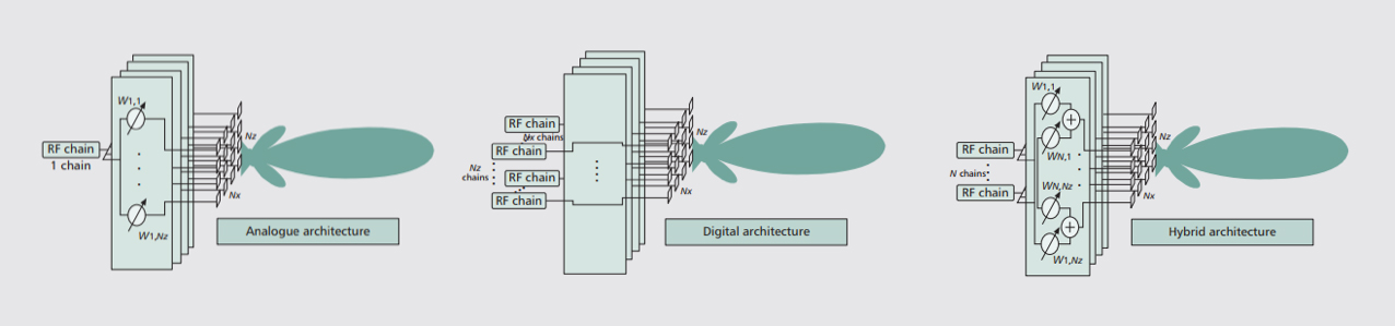
Analogue beamforming includes only a single RF chain for the whole NxxNz antenna array with one phase shifter per individual antenna array element, i.e. at least NxxNz phase shifters. In contrast, digital beamforming requires one RF chain per antenna array element, i.e. NxxNz RF chains in total, which is costly and power-consuming. But digital beamforming provides better performance with complete control over the antenna beam (direction, shape and nulls. Up to now, digital beamforming is being used for sub-6 GHz MIMO BTS antennas, where silicon technology performs well. However, at mm-waves, where larger array antennas are needed, digital beamforming becomes very costly and very power consuming. Analogue beamforming is the simplest architecture, but limited in performances e.g. multi-beam and MIMO are limited as its number of beams are fixed in hardware. This architecture is more suitable for point-to-point scenarios, where a single-beam antenna is enough.
There is also a third architecture, hybrid analogue/digital beamforming, which offers a compromise between analogue and digital architectures by balancing the analogue beamforming gain and
digital baseband processing. In this hybrid case, the antenna array is divided in Nz sub-arrays, each with Nx antenna array elements. Thus, this architecture requires one phase shifter per individual antenna array element, i.e. NxxNz phase shifters as for analogue beamforming, and one RF chain for each sub-array, i.e. Nz RF chains only, much less than for digital beamforming. This hybrid analogue/digital architecture enables multi-beam solutions (multi-user, MIMO to increase cell capacity) or the possibility to sum all the sub-arrays to form a single directive beam (to reach far-distant users by overcome propagation loss).
Hybrid analogue/digital architectures are the most suitable architecture for 5G mm-wave access antenna solutions both in terms of performance and cost. In this architecture, each sub-array requires high number of active RF components (phase shifter, LNA/PA and T/R switch per element), which increase the cost and the power consumption (hundreds of watts) of the antenna system in relation to analogue solutions. However, what is lost in terms of cost and power, is gained in terms of beam-forming flexibility and multi-beam capability.
ALCAN’s 5G solutions
"ALCAN’s solutions for 5G differs, depending on the application and type of link. Overall two types of solutions are provided: 1) Fully analogue beam-steering antenna arrays (ESA´s) for PtP links such as small cells, 2) Hybrid analogue/digital beam-steering antenna arrays with multi-beam capability (multi-beam ESA´s) for PtmP links such as Massive-MIMO base stations. "
ALCAN’s solutions for 5G differs, depending on the application and type of link. Overall two types of solutions are provided: 1) Fully analogue beam-steering antenna arrays (ESA´s) for PtP links such as small cells, 2) Hybrid analogue/digital beam-steering antenna arrays with multi-beam capability (multi-beam ESA´s) for PtmP links such as Massive-MIMO base stations. A general schematic representation of these two architectures are presented in Figure 3. As presented, in the hybrid architecture, an RF chain is used per sub-array and in the analogue architecture, an RF chain is used for the overall array.

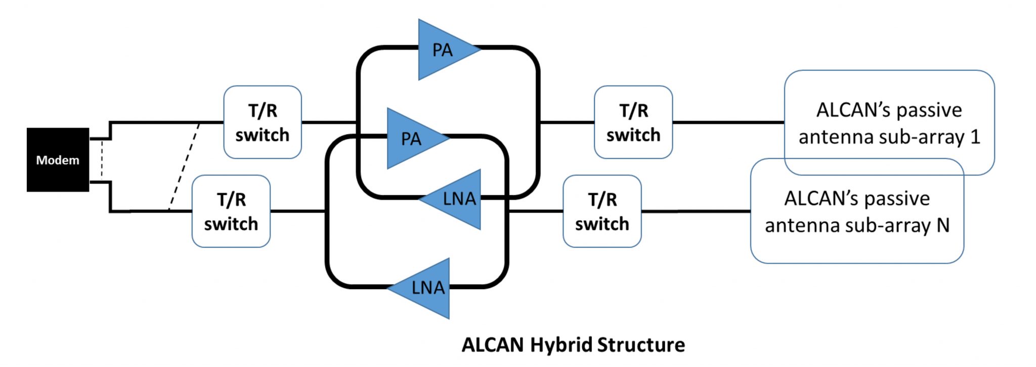
Figure 3: ALCAN Antenna Solution (a) ESA with fully analogue architecture, (b) Multi-beam ESA with hybrid architecture (sub-array).
As mentioned, the fully analogue architecture presented in Figure 3(a) is suitable for single-beam (single user, PtP) cases. This architecture offers the best performance in terms of cost and simplicity. For PtmP scenarios, on the other hand, the hybrid architecture is proposed as in Figure 3(b). This architecture offers the best compromise between beamforming flexibility and RF frontend cost/complicity. In comparison with MMIC-based hybrid beamforming antenna solutions, ALCAN’s smart antenna and its hybrid beamforming architecture require less RF components. The phase shifting is achieved by using ALCAN’s patented LC phase shifter technology, which has much lower cost (up to 100× cheaper) and power consumption (up to 30× lower) comparing to typical MMIC components. Moreover, ALCAN’s beamforming architecture does not require an LNA/PA and T/R switch per element but per sub-array.
"In comparison with MMIC-based hybrid beamforming antenna solutions, ALCAN’s smart antenna and its hybrid beamforming architecture require less RF components. The phase shifting is achieved by using ALCAN’s patented LC phase shifter technology, which has much lower cost (up to 100× cheaper) and power consumption (up to 30× lower) comparing to typical MMIC components. "
MMIC-based phased arrays typically use off the shelf beamforming ICs in market from companies such as Analog Devices, Anokiwave, Qorvo, etc. For example, A 8×8 antenna constituted using one of those commercial ICs would consume a power of around 20 Watts as to only 5.5 Watts for ALCAN’s energy efficient smart antenna solution. The difference, especially in terms of power consumption, becomes more significant for larger arrays. This is because the ALCAN energy-efficient solution’s power consumption does not increase linearly with increasing the number of array elements. For example, in case of a 16×16 elements array with 4 beams and to have a minimum EIRP of 60 dBm, ALCAN’s antenna overall power consumption will be around 15 Watts as to 65 Watts for antenna arrays based on Anokiwave’s ICs based on Silicon [3].
"For example, in case of a 16×16 elements array with 4 beams and to have a minimum EIRP of 60 dBm, ALCAN’s antenna overall power consumption will be around 15 Watts as to 65 Watts for antenna arrays based on Anokiwave’s ICs based on Silicon."
In a simplified case, as detailed in [4], for a random Dallas suburb with 800 houses per square kilometre 9 cell sites (with inter-site distance of 500m) are required to ensure a 1 Gbps service per user. Each cell site will require at least 3 access antennas with 120° coverage to ensure a full 360° coverage around the cell. This leads to use of minimum 27 access antennas per square kilometre. Per FCC, the maximum authorized EIRP level for an outdoor base station access antenna is 75 dBm and operator tend to use this maximum level to ensure highest coverage and capacity [5]. For silicon MMIC-based solutions, an antenna with an EIRP of 75 dBm will consume a power of hundreds of Watts (more than 200 Watts) as the ALCAN antenna will consume only around 35 Watts. The power required for an ALCAN antenna can be provided with a simple 35 Watts solar panel with an aperture of 48 cm×66 cm. Furthermore, if these number are recalculated for each base station antennas required per square meter, the high-power consumption of silicon-based solutions, more than 6000 Watts in contrary to only around 1000Watts with an ALCAN antenna, becomes more evident.
"For silicon MMIC-based solutions, an antenna with an EIRP of 75 dBm will consume a power of hundreds of Watts (more than 200 Watts) as the ALCAN antenna will consume only around 35 Watts. The power required for an ALCAN antenna can be provided with a simple 35 Watts solar panel with an aperture of 48 cm×66 cm."
"Furthermore, if these number are recalculated for each base station antennas required per square meter, the high-power consumption of silicon-based solutions, more than 6000 Watts in contrary to only around 1000Watts with an ALCAN antenna, becomes more evident."
In addition to being energy efficient, ALCAN’s smart antennas, in contrast to MMIC-based array antennas, benefit from cost-efficient phase shifting technology that leverages the existing mass production capabilities of LC Display production lines. By leveraging a large installed LCD production base as well as the low marginal cost of producing an additional LC panel, ALCAN is able to reduce the LC phase shifter costs by 100× to around $300/m² compared to semiconductor-based phase shifter costs which are at around $30,000/m².
"In addition to being energy efficient, ALCAN’s smart antennas, in contrast to MMIC-based array antennas, benefit from cost-efficient phase shifting technology that leverages the existing mass production capabilities of LC Display production lines."
CONCLUSION
Main factors that differentiate ALCAN’s smart antennas from other antenna solutions are:
- They are Energy-Efficient, as they have very low power consumption (only few watts), little heat dissipation, and thus, further cost savings.
- They are LOW COST electronically beam steerable. Compared to traditional active phased array antennas:
- They don’t use MMIC-based phased shifters (it is a “pure” passive solution)
- Their feeding network can be either fully analogue (backhaul/fronthaul) in single-beam ESA´s or hybrid analogue/digital in multi-beam ESA´s, depending on the application.
- Although being not discussed in detail in this article, they are real FLAT panel antennas (comparing to classical parabolic, lens and other quasi-optical antenna solutions) which has obvious advantages on several use cases such as for customer premises equipment.
These advantages become more considerable at mm-waves where either large array antennas are required, or large number of small antennas are deployed.
REFERENCES
[1] Mohammad Reza Dehghani Kodnoeih. “Development of next-generation 5G directive antennas at millimeter waves”. PhD thesis. UNIVERSITE DE NANTES, France, 2018.
[2] S. Sun, T. S. Rappaport, R. W. Heath, A. Nix and S. Rangan, “Mimo for millimeter-wave wireless communications: beamforming, spatial multiplexing, or both?,“ in IEEE Communications Magazine, vol. 52, no. 12, pp. 110-121, December 2014.
[3] Anokiwaves Inc. , “Introduction to All Silicon Millimeter-Wave 5G Arrays,” in Microwave Journal, March 2019
[4] Bror Peterson, “RF Front-end Technology and Tradeoffs for 5G mmWave Fixed Wireless Access” in Microwave Journal, November 2018.
[5] Federal Communications Commission. (2016, July). Use of Spectrum Bands Above 24 GHz for Mobile Radio Services, In the matter of GN Docket No. 14-177, IB Docket No. 15-256, RM-11664, WT Docket No. 10-112, IB Docket No. 97-95. Retrieved from https://apps.fcc.gov/edocs_public/attachmatch/FCC-16-89A1.pdf